Total Pageviews

Friday, October 30, 2015

Key Networking Terms


Key Terms


  • 10Base-T A Physical layer standard for networks that specifies baseband transmission, twisted pair media, and 10-Mbps throughput. 10Base-T networks have a maximum segment length of 100 meters and rely on a star topology.
  • 10GBase-ER A Physical layer standard for achieving 10-Gbps data transmission over single-mode, fiber-optic cable. In 10GBase-ER, the ER stands for extended reach. This standard specifies a star topology and segment lengths up to 40,000 meters.
     
  • 10GBase-EW A variation of the 10GBase-ER standard that is specially encoded to operate over SONET links.
  • 10GBase-LR A Physical layer standard for achieving 10-Gbps data transmission over single-mode, fiber-optic cable using wavelengths of 1310 nanometers. In 10GBase-LR, the LR stands for long reach. This standard specifies a star topology and segment lengths up to 10,000 meters.
  • 10GBase-LW A variation of the 10GBase-LR standard that is specially encoded to operate over SONET links.
  • 10GBase-SR A Physical layer standard for achieving 10-Gbps data transmission over multimode fiber using wavelengths of 850 nanometers. The maximum segment length for 10GBase-SR can reach up to 300 meters, depending on the fiber core diameter and modal bandwidth used.
  • 10GBase-SW A variation of the 10GBase-SR standard that is specially encoded to operate over SONET links.
  • 10GBase-T A Physical layer standard for achieving 10-Gbps data transmission over twisted pair cable. Described in its 2006 standard 802.3an, IEEE specifies Cat 6 or Cat 7 cable as the appropriate medium for 10GBase-T. The maximum segment length for 10GBase-T is 100 meters.
  • 100Base-FX A Physical layer standard for networks that specifies baseband transmission, multimode fiber cabling, and 100-Mbps throughput. 100Base-FX networks have a maximum segment length of 2000 meters. 100Base-FX may also be called Fast Ethernet.
  • 100Base-T A Physical layer standard for networks that specifies baseband transmission, twisted pair cabling, and 100-Mbps throughput. 100Base-T networks have a maximum segment length of 100 meters and use the star topology. 100Base-T is also known as Fast Ethernet.
  • 100Base-TX A type of 100Base-T network that uses two wire pairs in a twisted pair cable, but uses faster signaling to achieve 100-Mbps throughput. It is capable of full-duplex transmission and requires Cat 5 or better twisted pair media.
  • 1000Base-LX A Physical layer standard for networks that specifies 1-Gbps transmission over fiber-optic cable using baseband transmission. 1000Base-LX can run on either single-mode or multimode fiber. The LX represents its reliance on long wavelengths of 1300 nanometers. 1000Base-LX can extend to 5000-meter segment lengths using single-mode, fiber-optic cable. 1000Base-LX networks can use one repeater between segments.
  • 1000Base-SX A Physical layer standard for networks that specifies 1-Gbps transmission over fiber-optic cable using baseband transmission. 1000Base-SX runs on multimode fiber. Its maximum segment length is 550 meters. The SX represents its reliance on short wavelengths of 850 nanometers. 1000Base-SX can use one repeater.
  • 1000Base-T A Physical layer standard for achieving 1 Gbps over UTP. 1000Base-T achieves its higher throughput by using all four pairs of wires in a Cat 5 or better twisted pair cable to both transmit and receive signals. 1000Base-T also uses a different data encoding scheme than that used by other UTP Physical layer specifications.
  • 5-4-3 rule A guideline for 10-Mbps Ethernet networks stating that between two communicating nodes, the network cannot contain more than five network segments connected by four repeating devices, and no more than three of the segments may be populated.
  • 802.3ab The IEEE standard that describes 1000Base-T, a 1-gigabit Ethernet technology that runs over four pairs of Cat 5 or better cable.
  • 802.3ae The IEEE standard that describes 10-gigabit Ethernet technologies, including 10GBase-SR, 10GBase-SW, 10GBase-LR, 10GBase-LW, 10GBase-ER, and 10GBase-EW.
  • 802.3af The IEEE standard that specifies a way of supplying electrical Power over Ethernet (PoE). 802.3af requires Cat 5 or better UTP or STP cabling and uses power sourcing equipment to supply current over a wire pair to powered devices. PoE is compatible with existing 10Base-T, 100Base-TX, 1000Base-T, and 10GBase-T implementations.
  • 802.3an The IEEE standard that describes 10GBase-T, a 10-Gbps Ethernet technology that runs on Cat 6 or Cat 7 twisted pair cable.
  • 802.3u The IEEE standard that describes Fast Ethernet technologies, including 100Base-TX.
  • 802.3z The IEEE standard that describes 1000Base (or 1-gigabit) Ethernet technologies, including 1000Base-LX and 1000Base-SX.
  • access method A network’s method of controlling how nodes access the communications channel. For example, CSMA/CD (Carrier Sense Multiple Access with Collision Detection) is the access method specified in the IEEE 802.3 (Ethernet) standard.
  • active topology A topology in which each workstation participates in transmitting data over the network. A ring topology is considered an active topology.
  • broadcast domain Logically grouped network nodes that can communicate directly via broadcast transmissions. By default, switches and repeating devices such as hubs extend broadcast domains. Routers and other Layer 3 devices separate broadcast domains.
  • bus The single cable connecting all devices in a bus topology.
  • bus topology A topology in which a single cable connects all nodes on a network without intervening connectivity devices.
  • Carrier Ethernet A level of Ethernet service that is characterized by very high throughput and reliability and is used between carriers, such as NSPs.
  • Carrier Sense Multiple Access with Collision Detection See CSMA/CD.
  • circuit switching A type of switching in which a connection is established between two network nodes before they begin transmitting data. Bandwidth is dedicated to this connection and remains available until users terminate the communication between the two nodes.
  • collapsed backbone A type of backbone that uses a router or switch as the single central connection point for multiple subnetworks.
  • collision In Ethernet networks, the interference of one node’s data transmission with the data transmission of another node sharing the same segment.
  • collision domain The portion of an Ethernet network in which collisions could occur if two nodes transmit data at the same time. Switches and routers separate collision domains.
  • CSMA/CD (Carrier Sense Multiple Access with Collision Detection) A network access method specified for use by IEEE 802.3 (Ethernet) networks. In CSMA/CD, each node waits its turn before transmitting data to avoid interfering with other nodes’ transmissions. If a node’s NIC determines that its data have been involved in a collision, it immediately stops transmitting. Next, in a process called jamming, the NIC issues a special 32-bit sequence that indicates to the rest of the network nodes that its previous transmission was faulty and that those data frames are invalid. After waiting, the NIC determines if the line is again available; if it is available, the NIC retransmits its data.
  • daisy chain A group of connectivity devices linked together in a serial fashion.
  • data propagation delay The length of time data take to travel from one point on the segment to another point. On Ethernet networks, CSMA/CD’s collision detection routine cannot operate accurately if the data propagation delay is too long.
  • distributed backbone A type of backbone in which a number of intermediate connectivity devices are connected to one or more central connectivity devices, such switches or routers, in a hierarchy.
  • enterprise An entire organization, including local and remote offices, a mixture of computer systems, and a number of departments. Enterprise-wide computing takes into account the breadth and diversity of a large organization’s computer needs.
  • Ethernet II The original Ethernet frame type developed by Digital Equipment Corporation, Intel, and Xerox, before the IEEE began to standardize Ethernet. Ethernet II is distinguished from other Ethernet frame types in that it contains a 2-byte type field to identify the upper-layer protocol contained in the frame. It supports TCP/IP and other higher-layer protocols.
  • Fast Ethernet A type of Ethernet network that is capable of 100-Mbps throughput. 100Base-T and 100Base-FX are both examples of Fast Ethernet.
  • fault tolerance The capability for a component or system to continue functioning despite damage or malfunction.
  • Gigabit Ethernet A type of Ethernet network that is capable of 1000-Mbps, or 1-Gbps, throughput.
  • hybrid topology A physical topology that combines characteristics of more than one simple physical topology.
  • jamming A part of CSMA/CD in which, upon detecting a collision, a station issues a special 32-bit sequence to indicate to all nodes on an Ethernet segment that its previously transmitted frame has suffered a collision and should be considered faulty.
  • logical topology A characteristic of network transmission that reflects the way in which data are transmitted between nodes. A network’s logical topology may differ from its
  • physical topology. The most common logical topologies are bus and ring.
  • MPLS (multiprotocol label switching) A type of switching that enables any one of several Layer 2 protocols to carry multiple types of Layer 3 protocols. One of its benefits is the ability to use packet-switched technologies over traditionally circuit-switched networks. MPLS can also create end-to-end paths that act like circuit-switched connections.
  • modal bandwidth A measure of the highest frequency of signal a multimode fiber-optic cable can support over a specific distance. Modal bandwidth is measured in MHz-km.
  • multiprotocol label switching See MPLS.
  • packet switching A type of switching in which data are broken into packets before being transported. In packet switching, packets can travel any path on the network to their destination because each packet contains a destination address and sequencing information.
  • padding The bytes added to the data (or information) portion of an Ethernet frame to ensure this field is at least 46 bytes in size. Padding has no effect on the data carried by the frame.
  • parallel backbone A type of backbone that consists of more than one connection from the central router or switch to each network segment.
  • passive topology A network topology in which each node passively listens for, then accepts, data directed to it. A bus topology is considered a passive topology.
  • PD (powered device) On a network using Power over Ethernet, a node that receives power from power sourcing equipment.
  • physical topology The physical layout of the media, nodes, and devices on a network. A physical topology does not specify device types, connectivity methods, or addressing schemes. Physical topologies are categorized into three fundamental shapes: bus, ring, and star. These shapes can be mixed to create hybrid topologies.
  • PoE (Power over Ethernet) A method of delivering current to devices using Ethernet connection cables.
  • Power over Ethernet See PoE.
  • power sourcing equipment See PSE.
  • powered device See PD.
  • preamble The field in an Ethernet frame that signals to the receiving node that data are incoming and indicates when the data flow is about to begin.
  • PSE (power sourcing equipment) On a network using Power over Ethernet, the device that supplies power to end nodes.
  • QoS (quality of service) The result of specifications for guaranteeing data delivery within a certain period of time after their transmission.
  • quality of service See QoS.
  • ring topology A network layout in which each node is connected to the two nearest nodes so that the entire network forms a circle. Data are transmitted in one direction around the ring. Each workstation accepts and responds to packets addressed to it, then forwards the other packets to the next workstation in the ring.
  • serial backbone A type of backbone that consists of two or more internetworking devices connected to each other by a single cable in a daisy chain.
  • SFD (start-of-frame delimiter) A 1-byte field that indicates where the data field begins in an Ethernet frame.
  • signal bounce A phenomenon, caused by improper termination on a bus-topology network, in which signals travel endlessly between the two ends of the network, preventing new signals from getting through.
  • star topology A physical topology in which every node on the network is connected through a central connectivity device. Any single physical wire on a star network connects only two devices, so a cabling problem will affect only two nodes. Nodes transmit data to the device, which then retransmits the data to the rest of the network segment where the destination node can pick it up.
  • star-wired bus topology A hybrid topology in which groups of workstations are connected in a star fashion to connectivity devices that are networked via a single bus.
  • star-wired ring topology A hybrid topology that uses the physical layout of a star and the token-passing data transmission method.
  • start-of-frame delimiter See SFD.
  • switching A component of a network’s logical topology that manages how packets are filtered and forwarded between nodes on the network.
  • terminator A resistor that is attached to each end of a bus-topology network and that causes the signal to stop rather than reflect back toward its source.
backbone transmission technologies.

of the Smart grid glossary:

This table shows the stated data rates for the most important end-user and backbone transmission technologies.
TechnologySpeedPhysical MediumApplication
GSMmobile telephone service9.6 to 14.4 KbpsRF in space (wireless)Mobile telephone for business and personal use
High-Speed Circuit-Switched Data service (HSCSD)Up to 56 KbpsRF in space (wireless)Mobile telephone for business and personal use
Regular telephone service (POTS)Up to 56 Kbpstwisted pairHome and small business access
Dedicated 56Kbps on frame relay56 KbpsVariousBusiness e-mail with fairly large file attachments
DS064 KbpsAllThe base signal on a channel in the set of Digital Signal levels
General Packet Radio System (GPRS)56 to 114 KbpsRF in space (wireless)Mobile telephone for business and personal use
ISDNBRI: 64 Kbps to 128 Kbps
PRI: 23 (T-1) or 30 (E1) assignable 64-Kbps channels plus control channel; up to 1.544 Mbps (T-1) or 2.048 (E1)
BRI: Twisted-pair
PRI: T-1 or E1 line
BRI: Faster home and small business access
PRI: Medium and large enterprise access
IDSL128 KbpsTwisted-pairFaster home and small business access
AppleTalk230.4 KbpsTwisted pairLocal area network for Apple devices; several networks can be bridged; non-Apple devices can also be connected
Enhanced Data GSM Environment (EDGE)384 KbpsRF in space (wireless)Mobile telephone for business and personal use
satellite400 Kbps (DirecPC and others)RF in space (wireless)Faster home and small enterprise access
frame relay56 Kbps to 1.544 MbpsTwisted-pair or coaxial cableLarge company backbone for LANs to ISP
ISP to Internet infrastructure
DS1/T-11.544 MbpsTwisted-pair, coaxial cable, or optical fiberLarge company to ISP
ISP to Internet infrastructure
Universal Mobile Telecommunications Service (UMTS)Up to 2 MbpsRF in space (wireless)Mobile telephone for business and personal use (available in 2002 or later)
E-carrier2.048 MbpsTwisted-pair, coaxial cable, or optical fiber32-channel European equivalent of T-1
T-1C (DS1C)3.152 MbpsTwisted-pair, coaxial cable, or optical fiberLarge company to ISP
ISP to Internet infrastructure
IBM Token Ring/802.54 Mbps (also 16 Mbps)Twisted-pair, coaxial cable, or optical fiberSecond most commonly-used local area network after Ethernet
DS2/T-26.312 MbpsTwisted-pair, coaxial cable, or optical fiberLarge company to ISP
ISP to Internet infrastructure
Digital Subscriber Line (DSL)512 Kbps to 8 MbpsTwisted-pair (used as a digital, broadband medium)Home, small business, and enterprise access using existing copper lines
E-28.448 MbpsTwisted-pair, coaxial cable, or optical fiberCarries four multiplexed E-1 signals
cable modem512 Kbps to 52 Mbps
(see "Key and explanation" below)
Coaxial cable (usually uses Ethernet); in some systems, telephone used for upstream requestsHome, business, school access
Ethernet10 Mbps10BASE-T (twisted-pair); 10BASE-2 or -5 (coaxial cable); 10BASE-F (optical fiber)Most popular business local area network (LAN)
IBM Token Ring/802.516 Mbps (also 4 Mbps)Twisted-pair, coaxial cable, or optical fiberSecond most commonly-used local area network after Ethernet
E-334.368 MbpsTwisted-pair or optical fiberCarries 16 E-l signals
DS3/T-344.736 MbpsCoaxial cableISP to Internet infrastructure
Smaller links within Internet infrastructure
OC-151.84 MbpsOptical fiberISP to Internet infrastructure
Smaller links within Internet infrastructure
High-Speed Serial Interface (HSSI)Up to 53 MbpsHSSI cableBetween router hardware and WAN lines
Short-range (50 feet) interconnection between slower LAN devices and faster WAN lines
Fast Ethernet100 Mbps100BASE-T (twisted pair); 100BASE-T (twisted pair); 100BASE-T (optical fiber)Workstations with 10 Mbps Ethernet cards can plug into a Fast Ethernet LAN
Fiber Distributed-Data Interface (FDDI)100 MbpsOptical fiberLarge, wide-range LAN usually in a large company or a larger ISP
T-3D (DS3D)135 MbpsOptical fiberISP to Internet infrastructure
Smaller links within Internet infrastructure
E-4139.264 MbpsOptical fiberCarries 4 E3 channels
Up to 1,920 simultaneous voice conversations
OC-3/SDH155.52 MbpsOptical fiberLarge company backbone
Internet backbone
E-5565.148 MbpsOptical fiberCarries 4 E4 channels
Up to 7,680 simultaneous voice conversations
OC-12/STM-4622.08 MbpsOptical fiberInternet backbone
Gigabit Ethernet1 GbpsOptical fiber (and "copper" up to 100 meters)Workstations/networks with 10/100 Mbps Ethernet plug into Gigabit Ethernet switches
OC-241.244 GbpsOptical fiberInternet backbone
SciNet2.325 Gbps (15 OC-3 lines)Optical fiberPart of the vBNS backbone
OC-48/STM-162.488 GbpsOptical fiberInternet backbone
OC-192/STM-6410 GbpsOptical fiberBackbone
OC-25613.271 GbpsOptical fiberBackbone
Key and Explanation

Digital Signal 0 (DS0) is a basic digital signaling

Digital Signal 0 (DS0) is a basic digital signaling rate of 64 kilobits per second (kbit/s), corresponding to the capacity of one analog voice-frequency-equivalent channel.[1] The DS0 rate, and its equivalents E0 and T0, form the basis for the digital multiplex transmission hierarchy in telecommunications systems used in North America, Europe, Japan, and the rest of the world, for both the early plesiochronous systems such as T-carrier and for modern synchronous systems such as SDH/SONET.
The DS0 rate was introduced to carry a single digitized voice call. For a typical phone call, the audio sound is digitized at an 8 kHz sample rate, or 8000 samples per second, using 8-bit pulse-code modulation for each of the samples. This results in a data rate of 64 kbit/s.
Because of its fundamental role in carrying a single phone call, the DS0 rate forms the basis for the digital multiplex transmission hierarchy in telecommunications systems used in North America. To limit the number of wires required between two involved in exchanging voice calls, a system was built in which multiple DS0s are multiplexed together on higher capacity circuits. In this system, twenty-four (24) DS0s are multiplexed into a DS1 signal. Twenty-eight (28) DS1s are multiplexed into a DS3. When carried over copper wire, this is the well-known T-carrier system, with T1 and T3 corresponding to DS1 and DS3, respectively.
Besides its use for voice communications, the DS0 rate may support twenty 2.4 kbit/s channels, ten 4.8 kbit/s channels, five 9.67 kbit/s channels, one 56 kbit/s channel, or one 64 kbit/s clear channel.
E0 (standardized as ITU G.703) is the European equivalent of the North American DS0 for carrying . However, there are some subtle differences in implementation. Voice signals are encoded for carriage over E0 according to ITU G.711. Note that when a T-carrier system is used as in North America, robbed bit signaling can mean that a DS0 channel carried over that system is not an error-free bit-stream. The out-of-band signaling used in the European E-carrier system avoids this.

T1 Line Speed, DS1 Line Speed, T3 Bandwidth Speed, DS3 ...

Bandwidth Chart
ContactGRC
DFW/Texas
940-591-6805
Jacksonville Fl
904-412-3009
Email GRC


TypeRateAdditional info

ISDN:
BRI128KbpsISDN 2 64KB+1 16KD
PRI(na)1.480MbpsISDN 23B+1D (all 64K) ~ T1
PRI(eur)1.930MbpsISDN 30B+1D (all 64K) ~ E1

x
DSL:
ADSL640+Kbps up/
1.544+Mbps down
Asymmetric Digital Subscriber Line
Nonmatching send/receive transmission rates
HDSL784+KbpsTypically matching send/receive rates, can reach T1 speeds
SDSL768KbpsSingle Line Digital Subscriber Line aka HDSL2
VDSL19.2Mbps up/
51.84Mbps down
Very high rate Digital Subscriber Line
IDSL128KbpsEffectively ISDN over low quality non-CAT5 copper
with no voice capabilities
RADSLADSLRate Adaptive Digital Subscriber Line
ADSL that automatically adapts rates depending on
transmission medium quality
ANSI T1.413ADSLOfficial name for ADSL

T Carrier:
T11.544Mbps24 DS0 channels, equivalent to 1 DS1
T1C3.152Mbps48 channels
T26.312Mbps96 channels
T344.736Mbps672 channels
T4274.176Mbs4032 channels
E12.048Mbps30 64Kbps channels + 2 64Kbps D, aka European T1
DS064Kbps1 channel, same rate in NA, Japan, and Europe
DS11.544Mbps24 channels (T1)
DS1C3.152Mbps48 channels (T1C)
DS26.312Mbps96 channels (T2)
DS344.736Mbps672 channels (T3)
DS4274.176Mbps4032 channels (T4)
DS1 Japan1.544Mbps24 channels
DS2 Japan6.312Mbps96 channels
DS3 Japan32.064Mbps480 channels
DS4 Japan97.728Mbps1440 channels
DS5 Japan400.352Mbps5760 channels
DS1 Euro2.048Mbps30 channels + 2 D channels (E1)
DS2 Euro8.448Mbps120 channels + 2 D
DS3 Euro34.368Mbps480 channels + 2 D
DS4 Euro139.268Mbps1920 channels + 2 D
DS5 Euro565.148Mbps7680 channels + 2 D

Optical Carrier:
OC-151.48MbpsOptical Carrier SONET - All OC-n are 51.48*n Mbps
OC-3155.52MbpsOptical Carrier SONET
OC-12622.08MbpsOptical Carrier SONET
OC-482.4GbpsOptical Carrier SONET
OC-1929.6GbpsOptical Carrier SONET
OC-25613.1GbpsOptical Carrier SONET
OC-76840GbpsOptical Carrier SONET
Switched5656Kbps
Accunet56KbpsAT&T
Centronics Parallel200KB/sStandard PC parallel port
EPP400KB/sEnhanced Parallel Port
ECP2MB/sExtended Capabilities Parallel Port bidir, 8bit
HIPPI-32100MB/sANSI, 32 bit parallel
HIPPI-64200MB/sANSI, 64 bit parallel
IEEE 12842Mbpshigh speed centronics-like parallel
ESCON®10MB/sIBM, Fiber, max 5.6 miles
P1394400MbpsFirewire™, 63 devices max
USB12Mbps4 wire serial, 128 devices max
10Base210MB/sThin coax 607 feet (bus)
10Base510MB/sThick coax 1640 feet (bus)
10BaseT10MB/sTwisted Pair 328 feet (star)
10BaseF10MB/sFiber 1.2 miles (star)
100BaseT100MB/sTwisted Pair
Arcnet®2.5Mbps
CDPD19.2KbpsCellular Digital Packet Data
DDS56KbpsAT&T
FDDI100MbpsANSI, Fiber, 2 Kilometers max
FDSE20MbpsFull Duplex Switched Ethernet
G.7032.048Mbps
HSSI53Mbps
Lattisnet®10 MbpsSynoptics ethernet
LocalTalk®230.4Kbpstwisted pair
Starlan1MbpsAT&T twisted pair
Type A Coax2.35MbpsIBM, coax
Data collected from various sources including: Newton's Telecom Dictionary 13th ed., Black Box..., Byte Magazine, PC Magazine, ...

Wednesday, October 28, 2015

Wavelength Division Multiplexing (WDM)

Wavelength Division Multiplexing (WDM)


Why Is WDM Used?

          With the exponential growth in communications, caused mainly by the wide acceptance of the Internet, many carriers are finding that their estimates of fiber needs have been highly underestimated. Although most cables included many spare fibers when installed, this growth has used many of them and new capacity is needed. 

Three methods exist for expanding capacity:
1) installing more cables,
2) increasing system bitrate to multiplex more signals or
3) wavelength division multiplexing.

          Installing more cables will be the preferred method in many cases, especially in metropolitan areas, since fiber has become incredibly inexpensive and installation methods more efficient (like mass fusion splicing.)


But if conduit space is not available or major construction is necessary, this may not be the most cost effective.

          Increasing system bitrate may not prove cost effective either. Many systems are already running at SONET OC-48 rates (2.5 GB/s) and upgrading to OC-192 (10 GB/s) is expensive, requires changing out all the electronics in a network, and adds 4 times the capacity, more than may be necessary.
         

The third alternative, wavelength division multiplexing (WDM), has proven more cost effective in many instances. It allows using current electronics and current fibers, but simply shares fibers by transmitting different channels at different wavelengths (colors) of light. Systems that already use fiber optic amplifiers as repeaters also do not require upgrading for most WDM systems.


How Does WDM Work?

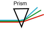
          It is easy to understand WDM. Consider the fact that you can see many different colors of light - reg, green, yellow, blue, etc. all at once. The colors are transmitted through the air together and may mix, but they can be easily separated using a simple device like a prism, just like we separate the "white" light from the sun into a spectrum of colors with the prism.


Figure 1. Separating a beam of light into its colors
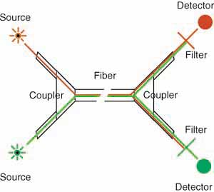
This technique was first demonstrated with optical fiber in the early 80s when telco fiber optic links still used multimode fiber. Light at 850 nm and 1300 nm was injected into the fiber at one end using a simple fused coupler. At the far end of the fiber, another coupler split the light into two fibers, one sent to a silicon detector more sensitive to 850 nm and one to a germanium or InGaAs detector more sensitive to 1300 nm. Filters removed the unwanted wavelengths, so each detector then was able to receive only the signal intended for it.

Figure 2. WDM with couplers and filters


By the late 80s, all telecom links were singlemode fiber, and coupler manufactures learned how to make fused couplers that could separate 1300nm and 1550 nm signals adequately to allow WDM with simple, inexpensive components. However, these had limited usefulness, as fiber was designed differently for 1300nm and 1550 nm, due to the dispersion characteristics of glass. Fiber optimized at 1300 nm was used for local loop links, while long haul and submarine cables used dispersion-shifted fiber optimized for performance at 1550 nm. This simple version of WDM is widely used in fiber to the home (FTTH) applications. Signals are sent downstream to the subscriber at 1490 nm (and 1550 for analog CATV if used) and upstream at 1310 n. Read more on FTTH.
         

With the advent of fiber optic amplifiers for repeaters in the late 80s, emphasis shifted to the 1550 nm transmission band. WDM only made sense if the multiplexed wavelengths were in the region of the fiber amplifiers operating range of 1520 to 1560 nm. It was not long before WDM equipment was able to put 4 signals into this band, with wavelengths about 10 nm apart.
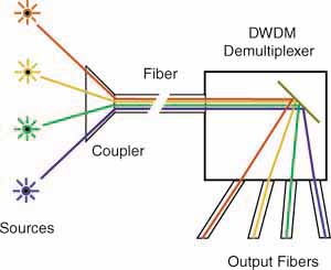
The input end of a WDM system is really quite simple. It is a simple coupler that combines all the inputs into one output fiber. These have been available for many years, offering 2, 4, 8, 16, 32 or even 64 inputs. It is the demultiplexer that is the difficult component to make.


Figure 3. WDM demultiplexer
The demultiplexer takes the input fiber and collimates the light into a narrow, parallel beam of light. It shines on a grating (a mirror like device that works like a prism, similar to the data side of a CD) which separates the light into the different wavelengths by sending them off at different angles. Optics capture each wavelength and focuses it into a fiber, creating separate outputs for each separate wavelength of light.


WDM to DWDM

          Current systems offer from 4 to 32 channels of wavelengths. The higher numbers of wavelengths has lead to the name Dense Wavelength Division Multiplexing or DWDM. The technical requirement is only that the lasers be of very specific wavelengths and the wavelengths are very stable, and the DWDM demultiplexers capable of distinguishing each wavelength without crosstalk.


Advantages of WDM

          A WDM system has some features that make them very useable. Each wavelength can be from a normal link, for example a OC-48 link, so you do not obsolete most of your current equipment. You merely need laser transmitterss chosen for wavelengths that match the WDM demultiplexer to make sure each channel is properly decoded at the receiving end.
If you use an OC-48 SONET input, you can have 4X2.5 GB/s = 10 GB/s up to 32 X 2.5 GB/s = 80 GB/s. While 32 channels are the maximum today, future enhancements are expected to offer 80-128 channels!
And you are not limited to SONET, you can use Gigabit Ethernet for example, or you can mix and match SONET and Gigabit Ethernet or any other digital signals! You can even mix in analog channels like CATV, as is done with  BPON FTTH systems.


Repeaters

          Another technology that facilitates DWDM is the development of fiber optic amplifiers for use as repeaters. They can amplify numerous wavelengths of light simultaneously, as long as all are in the wavelength range of the FO amplifier. They work best in the range of 1520-1560 nm, so most DWDM systems are designed for that range. Now that fiber has been made with less effect from the OH absorption bands at 1400 nm and 1600 nm, the possible range of DWDM has broadened considerably. Technology needs development for wider range fiber amplifiers to take advantage of the new fibers.


Applications

          Two obvious applications are already in use, submarine cables and extending the lifetime of cables where all fibers are being used. For submarine cables, DWDM enhances the capacity without adding fibers, which create larger cables and bulkier and more complicated repeaters. Adding service in areas where cables are now full is another good application.
But this technology may also reduce the cost on all land-based long distance communications links and new technology may lead to totally new network architectures.


Further Enhancements

          Imagine an all-optical network that uses DWDM, switches signals in the optical domain without converting signals to electronics, and can add or drop signals by inserting or withdrawing wavelengths at will. All this is being researched right now, and given the speed with which optical technology advances, an all-optical network may not be far in the future!

CWDM

          Coarse wavelength-division multiplexing is another variant of WDM. Generally CWDM refers to using lasers spaced 20 nm apart over the full range of 1260 to 1670 nm. It only works on low water peak fibers, where the high water absorption bands have been eliminated in the manufacture of the fiber.


http://www.thefoa.org/tech/dwdm.htm


Monday, October 26, 2015

Deploying Dual-Stack IPv4 and IPv6 Networks

Deploying Dual-Stack IPv4 and IPv6 Networks

Doing an IPv6 implementation project does not involve tearing down an aging IPv4 network and replacing it with a new IPv6-enabled network. Instead, the IPv4 and IPv6 networks will run in parallel in what the industry calls a "dual-stack" network. But IPv4 and IPv6 are so significantly different in design that network management tools designed for an IPv4 network may not work the same in an IPv6 environment.
In this second installment of a three-part series on IPv6 implementation, Network Computing looks at the issues involved in deploying an IPv6 network alongside an IPv4 network.
The IPv6 protocol was established because the number of IPv4 addresses is quickly running out. The IPv6 protocol creates a 128-bit address, four times the size of the 32-bit IPv4 standard, so there will be infinitely more available IP addresses. This will accommodate all the smartphones, tablets and other computers on the network, but also the coming proliferation of Internet-connected devices including refrigerators, cars, and myriad sensors in homes, buildings and on IP networks.
With IPv6, a company may have exponentially more Internet addresses to use, but also more to manage, says Leslie Daigle, chief Internet technology officer for the Internet Society (ISOC), a global nonprofit organization that certifies technical standards for the Internet.
"The IPv6 address space is so large and your allocation is likely to be larger than you need it to be," she says. "On the flip side, that makes it a lot harder to probe your entire network because it is a much larger space."
The volume of available IP addresses adds to the network operator's workload because they have to probe the "dark spaces" within the network where there are no assigned IP addresses. "The managing and making sure that no one is squatting in your address space is considered to be a possible additional challenge," says Daigle.
The ISOC has created a Web portal, Deploy 360, to share information about how to deploy an IPv6-compliant network. On the site are a number of case studies on how IPv6 rollouts went, including one about the project at Oxford University in the United Kingdom. In an online report, Oxford's Guy Edwards detailed a five-step plan for deploying IPv6 alongside the existing IPv4 network.
First, Edwards advises, the organization should perform a network device audit, identifying all the routers, switches and firewalls on the network, as well as what specific versions of hardware and software are running. With the help of networking vendors, the next step is to determine which of the devices are already IPv6-compliant. He also advises that network administrators run a test on a particular IPv6 device to make sure that the software application to run on the network works.

 http://www.informationweek.com/